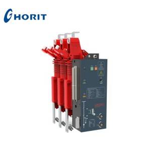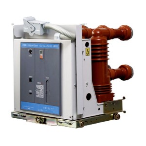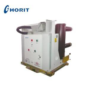
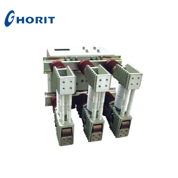
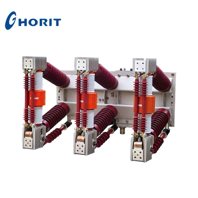
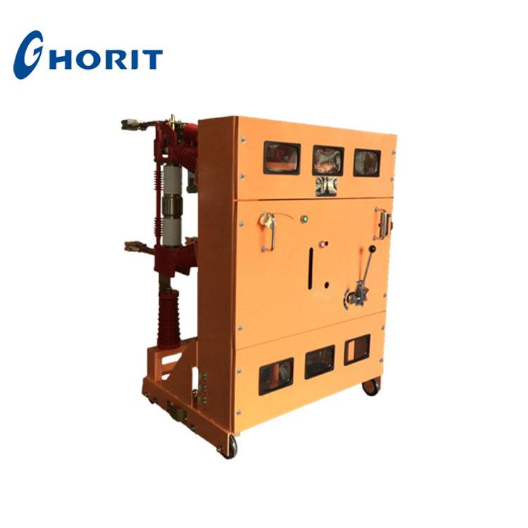
ZN12-12/40.5 indoor HV vacuum circuit breaker is a 3-phase AC 50Hz 12kV/40.5KV indoor switch equipment.
♦ Installation way: withdrawable type, fixed type;
♦ Operating mechanism: spring ope rating mechanism;
♦ Application: switchgear GBC-35, JYN1-35.
Environmental Conditions
♦ Ambient temperature: -25°C~+40°C;
♦ Altitude: <1000m;
♦ Relative humidity: daily average <95%, monthly average <90%;
♦ Earthquake intensity: <8 level;
♦ Places without fire, explosion hazard, serious filthy, chemical corrosion, as well as intense vibration.
Main Technical Parameters
ZN12-12
| No | Item |
Unit |
Value |
||||
| 1 | Rated voltage |
kV |
|||||
| 2 | Rated current |
A |
630, 1250, 1600 |
1250, 1600,2000, 2500,3150 |
2000, 2500, 3150,4000 |
||
| 3 | Rated short circuit breaking current |
kA |
20 |
25 |
31.5 |
40 |
50 |
| 4 | Dynamic stability current (peak) |
kA |
50 |
63 |
80 |
100 |
125 |
| 5 | 4s thermal stability current |
kA |
20 |
25 |
31.5 |
40/3s |
50/3s |
| 6 | Rated short circuit making current |
kA |
50 |
63 |
80 |
100 |
125 |
| 7 | Short circuit current breaking number | times |
30 |
12 |
|||
| 8 | Rated operating sequence |
CO-0.3S-CO-180S-CO |
O-180S-CO-180S-CO |
||||
| 9 | Mechanical life | times |
10000 |
6000 |
|||
| 10 | Rated current breaking number | times |
10000 |
6000 |
|||
| 11 | Rated lightning impulse withstand voltage (full wave) |
kV |
75 |
||||
| 12 | Rated short time power frequency withstand current (1 min) |
kV |
42 |
||||
| 13 | Closing time |
ms |
≤75 |
||||
| 14 | Opening time |
ms |
≤65 |
||||
| 15 | Power and rated voltage of energy storage motor |
W/V |
275W/ 110V, 220V |
||||
| 16 | Energy storage time |
s |
<15 |
||||
| No |
Item |
Unit |
Value |
| 17 | Rated voltage of closing coil |
V |
110V, 220V |
| 18 | Rated voltage of opening coil |
V |
|
| 19 | Rated voltage of interlock coil |
V |
|
| 20 | Rated current of release |
A |
5 |
| 21 | Rated current of auxiliary switch |
A |
AC10A, DC5A |
ZN12-40.5
| No | Item |
Unit |
Value |
|
| 1 | Rated voltage |
kV |
40.5 |
|
| 2 | Rated current |
A |
1250, 1600, 2000 |
1250, 1600,2000,2500 |
| 3 | Rated short circuit breaking current |
kA |
20, 25 |
31.5 |
| 4 | Dynamic stability current (peak) |
kA |
50, 63 |
80 |
| 5 | 4s thermal stability current |
kA |
20, 25 |
31.5 |
| 6 | Rated short circuit making current (peak) |
kA |
50, 63 |
80 |
| 7 | Short circuit current breaking number | times |
30 |
20 |
| 8 | Rated operating sequence |
CO-0.3S-CO-180S-CO |
||
| 9 | Rated lightning impulse withstand voltage (full wave) |
kV |
180 |
|
| 10 | Rated short time power frequency withstand current (1 min) |
kV |
95 |
|
|
11 |
Closing time |
ms |
≤90 |
|
| 12 | Opening time |
ms |
≤75 |
|
| 13 | Mechanica! life | times |
10000 |
60000 |
| 14 | Rated current breaking number | times |
10000 |
60000 |
| 15 | Rated capacitor bank breaking current |
A |
630 |
|
| Power of energy storage motor |
W |
275 |
||
| 17 | Rated voltage of energy storage motor |
V |
≃110V, 220V | |
|
18 |
Energy storage time |
s |
≤15 |
|
|
19 |
Rated voltage of closing and opening coil |
V |
≃110V, 220V |
|
|
20 |
Rated current of overcurrent release |
A |
5 |
|
|
21 |
Rated current of auxiliary switch |
A |
AC10A, DC5A |
|
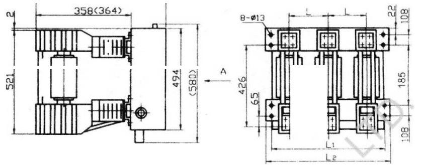
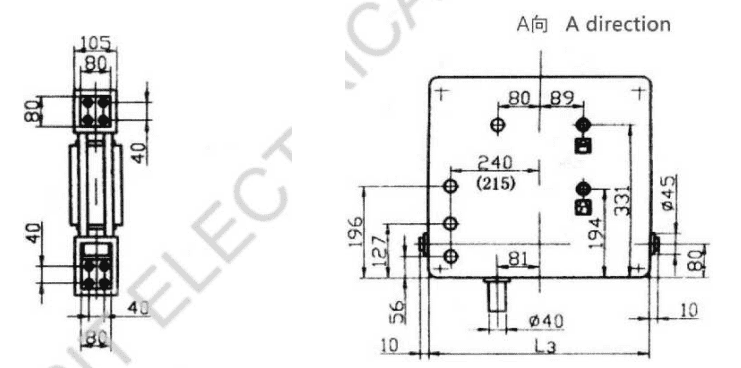
General Structure Drawing and Installation Size (unit: mm)
♦ ZN12-12 (inclined mounted)
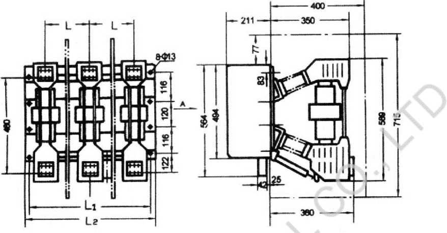
Note: dimension 360mm is for current above 2000A, under 2000A, the dimension is 350mm.
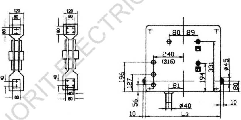
Note, in the figure, (215) means when L3=516mm, the dimension is 215mm.
Under 1600A: upper and lower outlet terminal hole 2-M12
Above 2000A: upper and lower outlet terminal hole 4-M12
|
Type |
L |
L1 |
L2 |
L3 |
Remarks |
|
ZN12-12 |
210 |
586 |
610 |
516 |
With inter-phase partition |
|
230 |
620 |
650 |
565 | ||
|
250 |
700 |
740 |
565 | ||
|
275 |
696 |
720 |
516 |
♦ ZN12-12B (flush mounted)(569〈575)
Note: (575) and (364) mean when short circuit breaking current is 40kA or above, the dimensions are 575mm, 364mm.
Upper and lower outlet terminal hole 4-M12
Note: (215) means when L3=516mm; the dimension is 215mm.
|
Type |
L |
L1 |
L2 |
L3 |
|
ZN12-12B |
210 |
586 |
610 |
516 |
|
230 |
620 |
650 |
565 |
|
|
250 |
700 |
740 |
565 |
|
|
275 |
696 |
720 |
516 |
Remarks With inter-phase partition
-
VSG-24 Series Indoor High Voltage Vacuum Circui...
-
VHK9-12 TYPE INTEGRATED COMBINED VACUUM CIRCUIT...
-
100% Original Factory China 11kv 12kv High Volt...
-
VSM-12 series permanent magnet-type indoor vacu...
-
ZN85-40.5 Series Indoor High Voltage Vacuum Cir...
-
VS1-12 Series Indoor High Voltage Vacuum Circui...