1. Outline
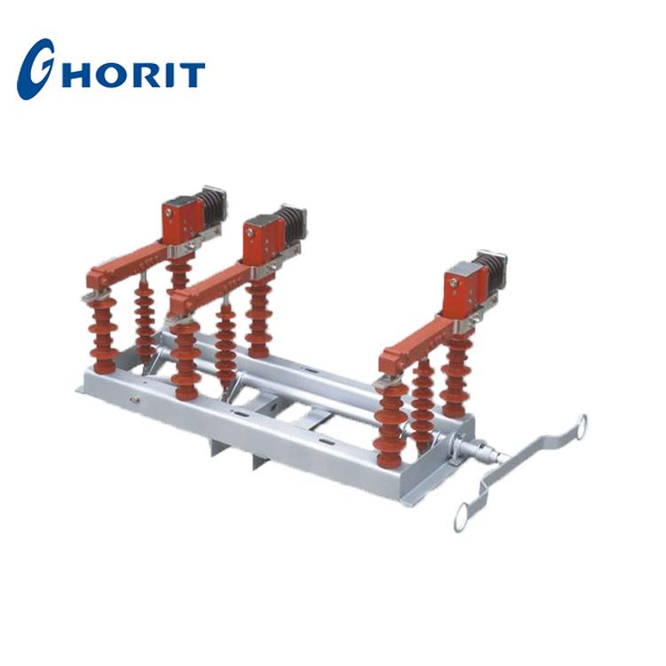
FZW32-12 type outdoor high voltage disconnecting vacuum break load switch is a new type of load switch which is the integration of mature experience of domestic existing load switch and advanced technology design of external. This load break switch is composed of disconnector, vacuum interrupter and operating mechanism and other parts. By using the principle of vacuum interrupter, with strong arcing ability, reliable performance, long service life, small volume, no explosion danger, no pollution etc advantage. The product can be used in transmission and distribution system of electric power, metallurgy, mine, chemical industry and other departments as control equipment, especially suitable for frequent operation place.
2. Instruction
1.Use vacuum interrupter, without explosion hazard and no need maintenance.
2.Disconnector and three-phase vacuum interrupter are ganged, when opening, there is obvious disconnecting fracture.
3.All components use stainless steel material, the chassis uses stainless steel material or hot galvanizing coated with anti UV protection paint carbon steel, ensures product’s normal operation in outdoor environment.
4.Installation way mainly are single pole mounting and manual operation, also use motorized or remote control operation.
5.Widely used in rural and urban distribution network, railway and other distribution electricity circuit retrofit.
6.Great breaking capacity, safe, reliable, long electrical life, and can be operated frequently.
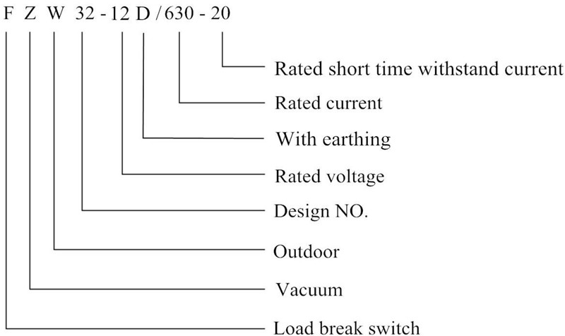
3. Type Description
4. Environmental Conditions
a. Altitude ≤1000m;
b. Ambient air temperature -30~+40℃;
c. Relative humidity: daily average ≤95%, monthly average ≤90%;
d. Without frequent violent vibration.
5. Technical Parameters
| NO. | Name | Unit | Value | |
| 1 | Rated voltage | KV | 12 | |
| 2 | Rated frequency | Hz | 50 | |
| 3 | Rated current | A | 630 | |
| 4 | Rated active load breaking current | A | 630 | |
| 5 | Rated closed loop breaking current | A | 630 | |
| 6 | 5%rated active load breaking current | A | 31. 5 | |
| 7 | Rated cable charging breaking current | A | 10 | |
| 8 | Rated breaking capacity of no-load transformer | KVA | 1600 | |
| 9 | Rated breaking capacitor bank current | A | 100 | |
| 10 | 1min power frequency withstand voltage: vacuum fracture/phase-to-phase, phase-to earth, disconnectingfracture | KV | 42/48 | |
| 11 | Lightning impulse withstand voltage: phase-to phase,phase-to-earth/disconnecting fracture | KV | 75/85 | |
| 12 | Rated short time withstand current(thermal stability) | KA | 20 | |
| 13 | Rated short-circuit duration | S | 4 | |
| 14 | Rated peak withstand current(dynamic stability) | KA | 50 | |
| 15 | Rated short-circuit closing current | KA | 50 | |
| 16 | Mechanical life | Times | 10000 | |
| 17 | Vacuum interrupter contact erosion limit | mm | 0.5 | |
| 18 | Manual operating torque | Nm | ≤200 | |
|
19 |
Load break switch vacuum interrupter assembling adjustment |
Clearance between opencontacts | mm | 5±1 |
| Average opening speed | m/s | 1.1±0.2 | ||
| Three-phase openingasynchronism | ms | <5 | ||
| Three-phase closingasynchronism | ms | <2 | ||
| Distance between chargedbodies and phase-to-earth | mm | >200 | ||
| Auxiliary circuit resistance | μΩ | ≥400 | ||
6. Installation Ways, Transverse Width and Phase-to-phase Distance
| Installation way | Transverse width | AB phase-to-phasedistance | BC phase-to-phasedistance |
| Single pole horizontal installation | 1300mm |
750mm |
320mm |
| Singe pole vertical installation | 1230mm |
500mm |
500mm |
| Singe pole vertical installation | 1050mm |
400mm |
400mm |
7. Basic Structure Drawing
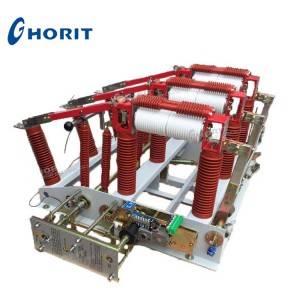
The load break switch with three-phase linkage, is mainly consist of frame, vacuum interrupter components, disconnector components and spring mechanism, disconnector and vacuum interrupter are fixed on frame via insulator, spring is fixed on frame.
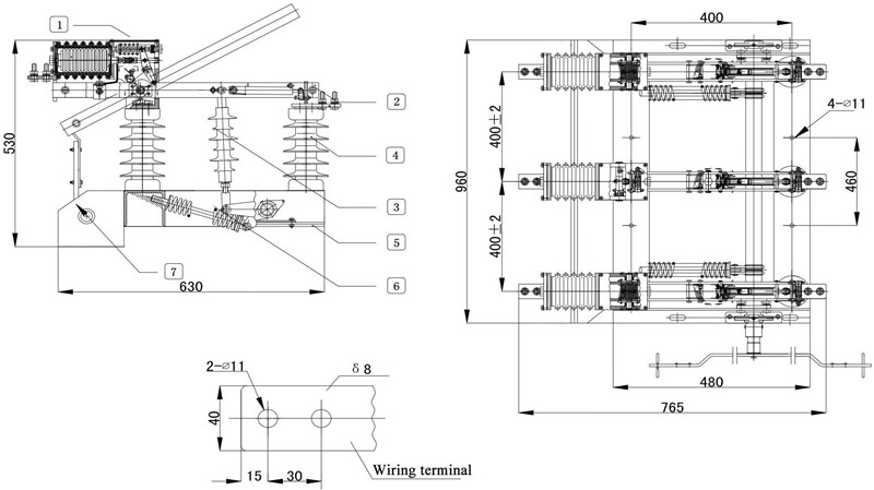
1.Vacuum interrupter 2. Disconnector components 3. Insulating rod
4. Insulator 5. Spring 6. Frame 7. Earthing components
Installation Ways and Mounting Bracket Schematic Diagram
Installation ways of load break switch include pole top installation, horizontal installation and single pole vertical installation.
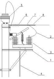
9.1. Single pole vertical installation (see figure)
1.Terminal
2.Hoop
3.Mounting bracket(long bracket, short bracket)
4.Load break switch
5.Pole
6.Power supply outgoing
7.Power supply incoming
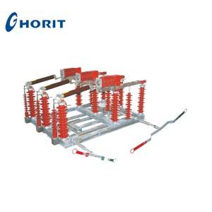
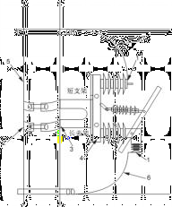
9.2. Horizontal installation (see figure)
1.Switch bracket components
2.Connecting cooper bar
3.Load break switch
4.Operating lever
5.CT
6.Insulator
7.Fork type lock
8.Strain clamp
9.3. Pole top installation (see figure)
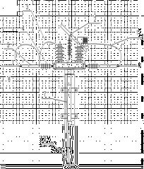
1.Connecting wire
2.Load break switch
3.Connecting cooper bar
4.Insulator
5.Fork type lock
6.Strain clamp
7.Switch bracket
8.Operating lever