
FN5-12 type indoor AC high voltage load brek switch (Hereinafter referred to as load break switch) apples to AC 50Hz 12kV network, for breaking load current and closing short circuit current. Load break switch with fuse can cut off short circuit current for switch protection.
The load break switch can be used with CS6-1 type manual operating mechanism, and this product special uses CS manual operating mechanism.

Application
FN5-12 type indoor AC high voltage load break switch (Hereinafter referred to as load break switch) applies to AC 50Hz 12kV network, for breaking load current and closing short circuit current. Load break switch with fuse can cut off short circuit current for switch protection.
The load break switch can be used with CS6-1 type manual operating mechanism, and this product special uses CS 口 manual operating mechanism.
Type and Meaning
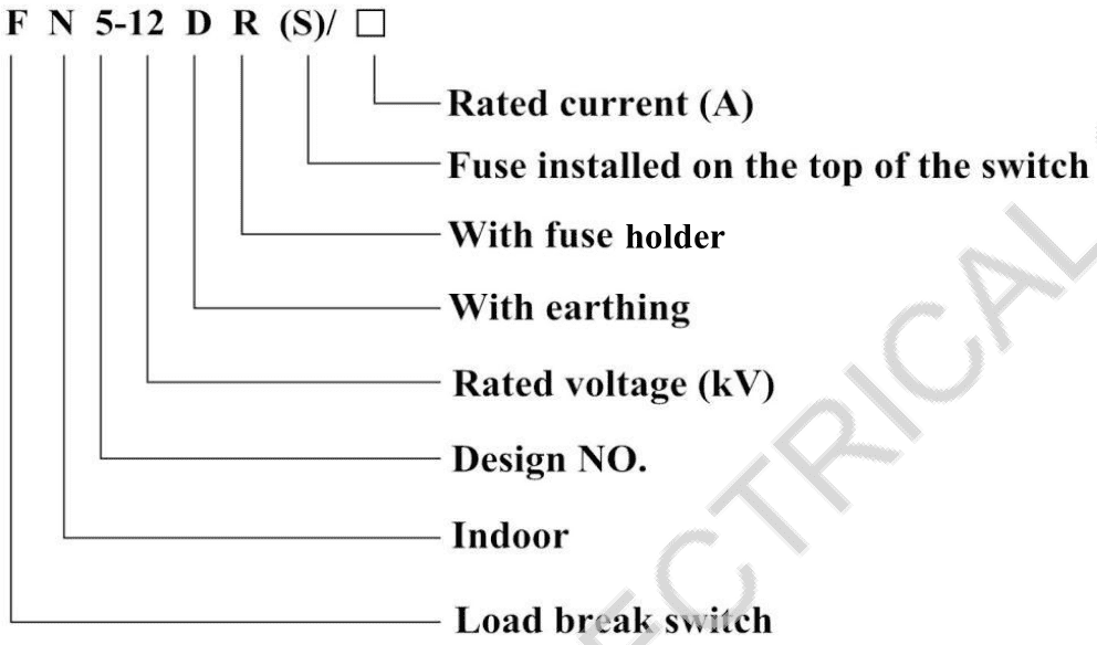
Use environment
a. Altitude < 1000m;
b. Ambient air teirr mFre: -25~+40°C, (motorized operating mechanism〉-5°C);
c. Relative humidity: daily average <95%, monthly average < 90% (+25 °C);
d. Ambient air without obvious pollution, like corrosive or flammable gas, water vapor, etc.
e. Wihtout requent strong vibration.
Technical data
4.1 Load break switch technical parameters table 1
| Name |
Unit |
Value |
| Rated voltage |
kV |
12 |
| Maximum working voltage |
kV |
12 |
| Rated frequency |
Hz |
5。 |
| Rated current |
A |
400 630 |
| Rated short time withstand current (thermal stability current) |
kA/S |
12.5/4 20/2 |
| Rated peak withstand current (dynamic stability current) |
kA |
31.5 50 |
| Rated closed loop breaking current |
A |
400 630 |
| Rated power loading breaking current |
A. |
400 630 |
| 5% rated power loading breaking current |
A |
20 31.5 |
| Rated cable charging breaking current |
A |
10 |
| Rated no load transformer breaking current | 1250kVA no-load
current of transformer |
|
| Rated short circuit closing current |
kA |
31.5 50 |
| Load current breaking times |
Load/times |
100%/20 30%/75 60%/35 5%/80 |
| 1min power frequency w; nstana voltage (RMS), phase-to-phase / isoktmg fracture |
kV |
42/48 |
| Power frequency v^tnstand voltage between isolating fractures |
kV |
53 |
| Lightning impulse withstand voltage to ground(peak), phase-to-phase/isolating fracture |
kV |
75/85 |
| Opening/closing operating torque |
Nm(N) |
90(80) 100(200) |
Note: FN5-12D grounded part of the load switch with short-circuit making current capacity.
4.2 Fuse technical parameter table2
|
Model |
Rated voltage KV |
Fuse Rated current A |
Rated breaking current KA |
Rated current of fuse-element |
|
RN3 |
12 |
50 |
12.5 |
2, 3, 5, 7.5, 12, 15,20,30, 40, 50 |
|
75 |
75 |
|||
|
100 |
100 |
|||
|
200 |
150 200 |
|||
| SDL*J |
12 |
40 |
50 |
6.3, 10, 16, 20, 25,31.5,40 |
|
SFL*J |
12 |
100 |
50, 63, 71, 80, 100 |
|
| SKL*J |
12 |
126 |
125 |
Appearance and Installation Dimensions (mm)
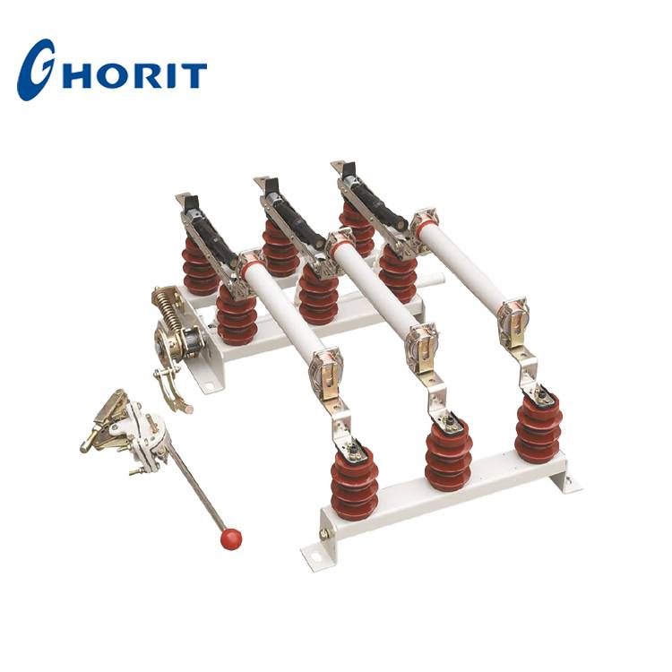
Fig. 1 FN5-12
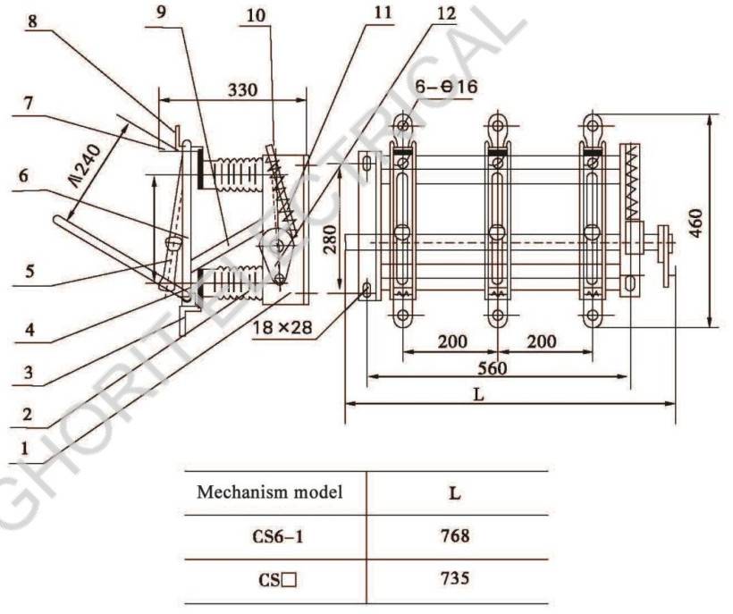
1. Framework 2. Post insulator 3. Bearing wiring board 4. Blade 5. Arc extinguisher
6. Torsional spring and its pin bearing 7. Guide bar 8. Wiring board 9. Lever
10. Load switch moving bearing 11. Spring charging mechanism 12. Operating mechanism
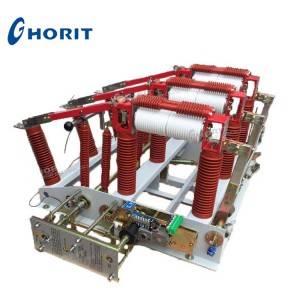
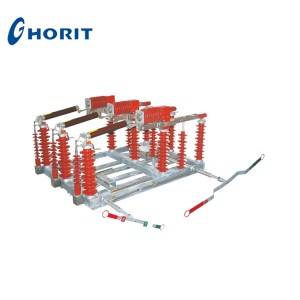
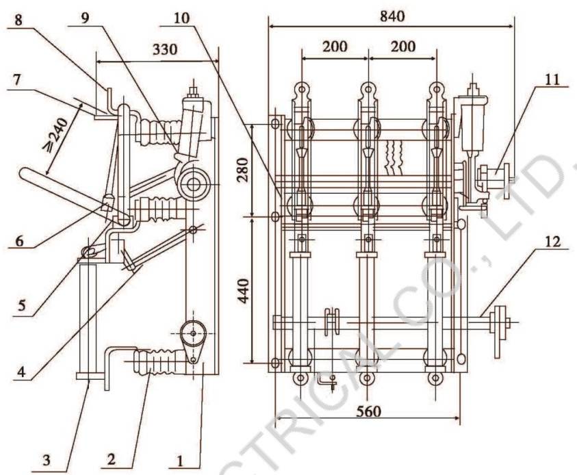
Fig. 2 FN5-12D

1. Framework 2. Earth blad , 3. 7 ,rth switch moving bearing 4. Post insulator
5. Earth moving bearing 6. Beaming wiring board 7. Blade 8. Arc extinguisher
9. Draw spring and + spring’s pin bearing 10. Guide bar 11. Wiring board 12. Lever
13.Load switch bearing 14. Load switch spring charging mechanism
15. Earth swl、h ^ring charging mechanism 16. Load switch operating mechanism
17. Er rth vi ch operating mechanism 18. Interlock mechanism
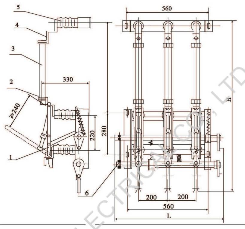
Fig. 3 FN5-12R(S)

1. FN5-12R load sv 2. Bering fuse wiring board 3. Fuse link 4. Fuse wiring board
5. Fuse base
Fig. 4 FN5-12DR

| Mechanism modelCS6-1
csn |
L Fuse model |
H |
h |
|
| SDL*J、SFL*J、SKL*J |
935 |
530 | ||
|
735 RN3-10 |
<75 |
990 |
585 | |
|
5=75 |
1040 |
635 | ||
1. FN5-12D load s.’<icn 2. Bering fuse wiring board 3. Fuse 4. Fuse wiring board
5. Fuse base
Fig. 4 FN5-12R(S)

1. FN5-12 load swi、c:i 2. Bering,se wiring board 3. Fuse 4. Fuse wiring board 5. Fuse base
Fig. 6 FN5-12DR(S)

1. FN5-12D switch 2. Bering fuse wiring board 3. Fuse 4. Fuse wiring board
5. Fus 二 6. Interlock mechanism
Fig. 7 FN5-12R(D)L
1. Under frame 2. Insulator 3. Fuse 4. Tripper device 5. Moving contact 6. Arc extinguisher
7. Guide bar 8. Static contact 9. Opening/closing mechanism 10. Interlock device
11. Load switch operating mechanism 12. Earth switch