
General
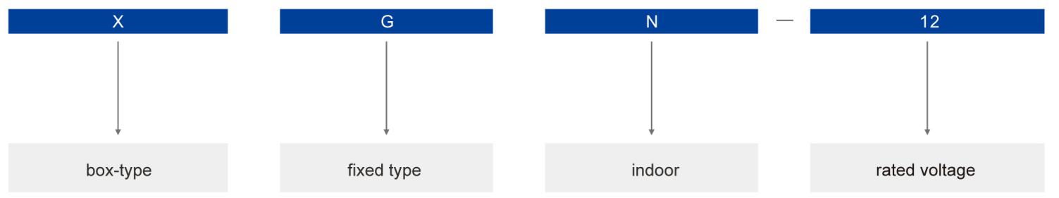
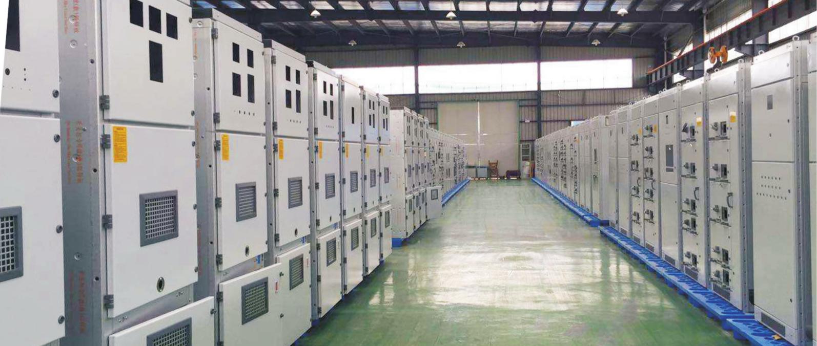
XGN-12 box-type fixed AC metal-enclosed switchgear (referred to as "switchgear"), suitable for rated voltage 3.6~12kV, 50Hz, rated current 630A~3150A three-phase AC single bus, double bus, single bus with bypass system , Used for receiving and distributing electric energy. It can meet the requirements of various types of power plants, substations (substations) and industrial and mining enterprises.
This product complies with the national standards GB3906 "Alternating-current metal-enclosed switchgear and controlgear for rated voltage above 3.6kV and up to and including 40.5kV", IEC60298 "A.C. metal-enclosed switchgear and controlgear for rated voltages above 1 kV and up to and including 52kV", and DL/T402, DL/T404 standards, and meets the "five prevention" interlocking requirements.
Normal Use Conditions
● Ambient air temperature: -15℃~+40℃.
● Humidity conditions:
Daily average relative humidity: ≤95%, daily average water vapor pressure ≤2.2kPa.
The monthly average relative humidity is 90%, and the monthly average water vapor pressure is 1.8kPa.
● Altitude: ≤4000m.
● Earthquake intensity: ≤8 degrees.
● The surrounding air should not be contaminated by corrosive or combustible gas, water vapor, etc.
● Places without frequent severe vibration.
● if use conditions exceeds the normal conditions specified by GB3906, the user and the manufacturer shall negotiate.
Type Description
Main Technical Parameters
|
Item |
Unit |
Value |
||
| Rated voltage |
kV |
3.6,7.2,12 |
||
| Rated current |
A |
630~3150 |
||
| Rated short circuit breaking current |
kA |
16,20,31.5,40 |
||
| Rated short circuit making current (peak) |
kA |
40,50,80,100 |
||
| Rated withstand current (peak) |
kA |
40,50,80,100 |
||
| Rated short time withstand current |
kA |
16,20,31.5,40 |
||
| Rated insulation level | 1min power frequency withstand voltage | Phase-to-phase, phase-to-earth |
kV |
24,32,42 |
| Across open contacts |
kV |
24,32,48 |
||
| Lightning impulse withstand voltage | Phase-to-phase, phase-to-earth |
kV |
40,60,75 |
|
| Across open contacts |
kV |
46,70,85 |
||
| Rated short circuit duration |
s |
4 |
||
| Protection degree |
IP2X |
|||
| Main wiring type |
Single bus segment and single bus with bypass |
|||
| Operating mechanism type |
Electromagnetic, spring charge |
|||
| Overall dimensions(W*D*H) |
mm |
1100X1200X2650 (normal type) |
||
| Weight |
kg |
1000 |
||
Structure
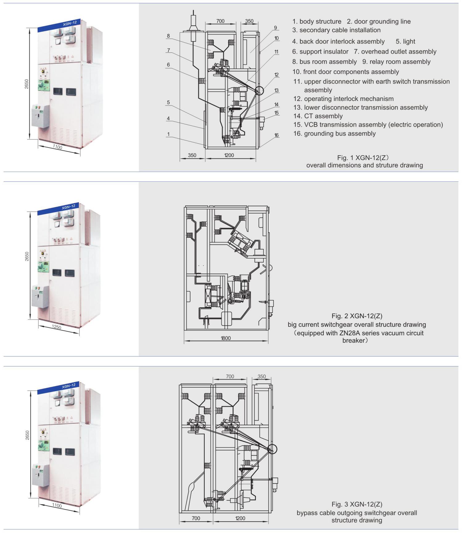
● XGN-12 switch cabinet is a metal-enclosed box structure. The frame of the cabinet is welded by angle steel. The cabinet is divided into circuit breaker room, busbar room, cable room, relay room, etc., separated by steel plates.
● The circuit breaker room is in the lower front of the cabinet. The rotation of the circuit breaker is connected with the operating mechanism by the tie rod. The upper wiring terminal of the circuit breaker is connected with the upper disconnector, the lower wiring terminal of the circuit breaker is connected with the current transformer, and the current transformer is connected with the wiring terminal of the lower disconnector. And the circuit breaker room is also equipped with a pressure release channel. If an internal arc occurs, the gas can release the pressure through the exhaust channel.
● The busbar room is in the upper part of the rear of the cabinet. In order to reduce the height of the cabinet, the busbars are arranged in a “pin” shape, supported by 7350N bending strength porcelain insulators, and the busbars are connected to the upper disconnector terminal, can be disconnected between the two adjacent cabinet busbars.
● The cable room is behind the lower part of the cabinet. The supporting insulator in the cable room can be equipped with voltage monitoring devices, and the cables are fixed on the bracket. For the main connection plan, this room is the contact cable room. The relay room is in the front of the upper part of the cabinet. The indoor installation board can be installed with various relays. There are terminal block brackets in the room. The door can be installed with secondary components such as indicating instruments and signal components. The top can also be equipped with a secondary small bus.
● The operating mechanism of the circuit breaker is installed on the left side of the front, and above it is the operating and interlocking mechanism of the disconnector. The switchgear is double-sided maintenance. The secondary components of the relay room, the maintenance operating mechanism, the mechanical interlocking and transmission parts, and the circuit breaker are checked and repaired in the front. The main bus and cable terminals are repaired at the back, and lights are installed in the circuit breaker room. Below the front door is provided with a grounding copper bus bar parallel to the width of the cabinet, with a cross section of 4X40mm.
● Mechanical interlocking: In order to prevent the disconnector with load, prevent the wrong opening and closing of the circuit breaker, and prevent the energized interval from entering by mistake; prevent the earth switch with electricity from closing; prevent the closing of the earth switch, the switch cabinet adopts the corresponding mechanical interlock.
The mechanical interlock operation principle of the chain is as follows:
● Power failure operation (operation-overhaul): The switch cabinet is in the working position, that is, the upper and lower disconnector and circuit breakers are in the closing state, the front and rear doors have been locked, and are in live operation. At this time, the small handle is in the working position. Firstly open the circuit breaker, and then pull the small handle to the "breaking interlock" position. At this time, the circuit breaker cannot be closed. Insert the operating handle into the lower disconnector operating hole and pull it down from the top to the lower disconnector opening position , Remove the handle, and then insert it into the upper disconnector operation hole, pull it down from the top to the upper disconnector opening position, then remove the operation handle, insert it into the operation hole of the earth switch, and push it from bottom to top to make the earth switch in the closing position, the small handle can be pulled to the "overhaul" position at this time. You can open the front door first, take out the key behind the door and open the back door. After the power failure operation is completed, the maintenance personnel will maintain and repair the circuit breaker room and cable room.
● Power transmission operation (overhaul-operation): If the maintenance has been completed and power is required, the operating procedure is as follows: close the back, remove the key and close the front door, and move the small handle from the "overhaul" position to the "disconnecting interlock" position. When the front door is locked and the circuit breaker cannot be closed, insert the operating handle into the operating hole of the earth switch and pull it down from top to bottom to make the earth switch in the open position. Remove the operating handle and insert it into the disconnector operating hole. Push down and up to make the upper disconnector in the closing position, remove the operating handle, insert it into the operating hole of the lower disconnector, and push from the bottom up to make the lower disconnector in the closing position, take out the operating handle, and pull the small handle to the working position, the circuit breaker can be closed.
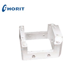
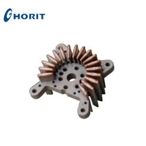
● Product overall dimensions and structure drawing (see Figure 1, Figure 2, Figure 3)